Week 3: Computer-Controlled Cutting
Individual Documentation: Laser Cutting Accuracy and Vinyl Cutting.
Group Work Reflection
You can access our collective machine characterization and laser cutting tests on the Group Work Page.
During the group assignment, I participated in testing the laser's power and speed settings on various materials. We characterized the lasercutter's focus, power, speed, rate, kerf, joint clearance, and types. I also successfully completed the lab's safety training. This experience was vital because it taught me how to accurately measure the Kerf. By understanding how much material the laser removes, I was able to adjust the parameters in my individual parametric kit, ensuring a perfect press-fit connection.
FabLab Individual Project Report: Laser Cutting Accuracy
Machine: Fusion Laser Cut
Material: HDF - 3mm
Objective: Design, lasercut, and document a parametric construction kit, accounting for the lasercutter kerf.
1. The Concept of Kerf
Kerf is the amount of the material removed by the laser during a cut.
- Impact: If not accounted for, holes become larger, and parts become smaller.
- Solution: we acount for kerf in our design to neutralize this effect and ensure a high-precision fit.
2. The Concept of Thickness
In Fusion 360, thickness could be defined as a User Parameter.
- Impact: When we consider the value of the slot width as Material Thickness - Kerf and Tab width as Material thickness + kerf, then changing this variable automatically updates all cutting parameters, including slot widths and tab width.
- Note: Actual material thickness (like "3mm" HDF) often varies slightly from the nominal value.
Why are these changes important for our design?
Changing these two parameters is done for three key reasons:
A) Creating a Friction Connection (Press-fit)
- If we want two parts to lock together without the use of glue, the Kerf value must be calculated precisely.
- If the Kerf is not calculated correctly, the parts will either fail to interlock properly or will be too loose after cutting.
- By applying the appropriate Offset, the parts will securely snap together using only hand pressure.
B) Parametric Design and Flexibility
- In Fusion 360, it is necessary to define thickness as a variable (Parameter); this way, when the material changes, there is no need to redesign the entire model from scratch.
- We change the thickness value corresponding to the material being used, and the entire model (including all placements and joints) is updated through an integrated chain reaction.
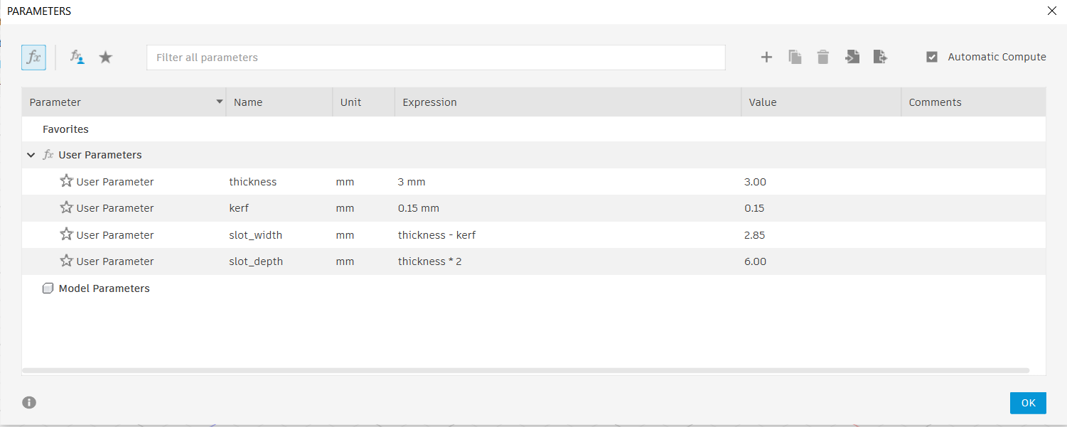
Fig. 1: Defining user parameters for thickness and kerf in Fusion 360.
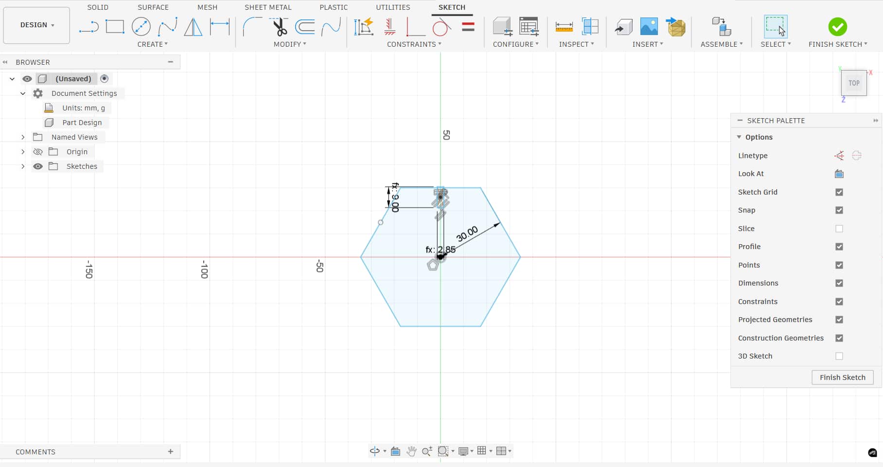
Fig. 2: Starting the initial 2D sketch for the construction kit part.
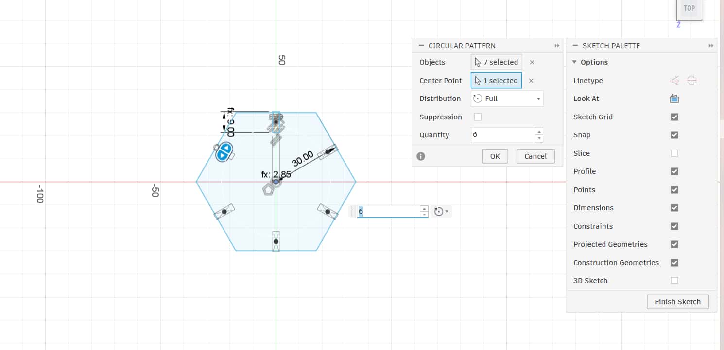
Fig. 3: Applying parametric formulas to the slot dimensions.
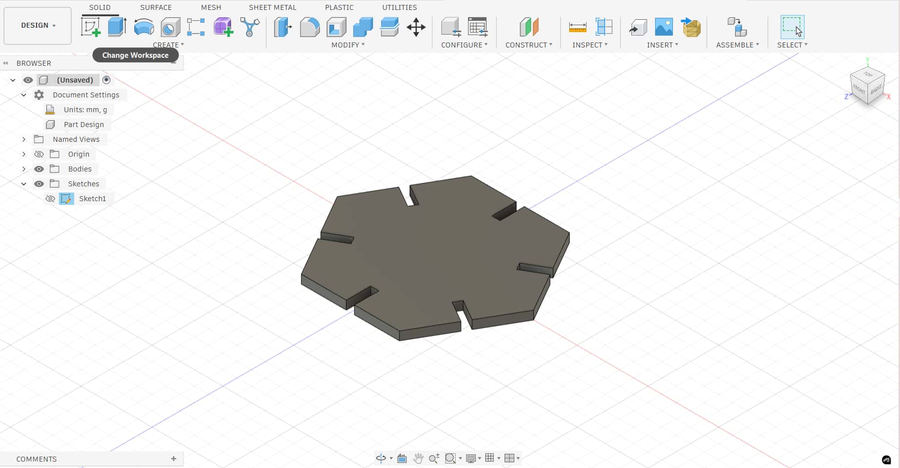
Fig. 4: Finalizing the sketch constraints and geometric relations.
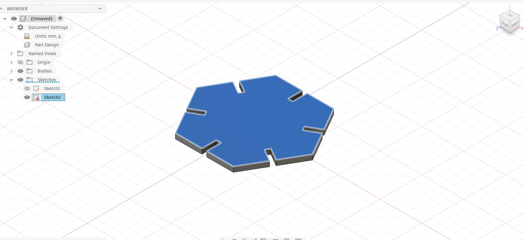
Fig. 5: Extruding the sketch to create a 3D part based on material thickness.
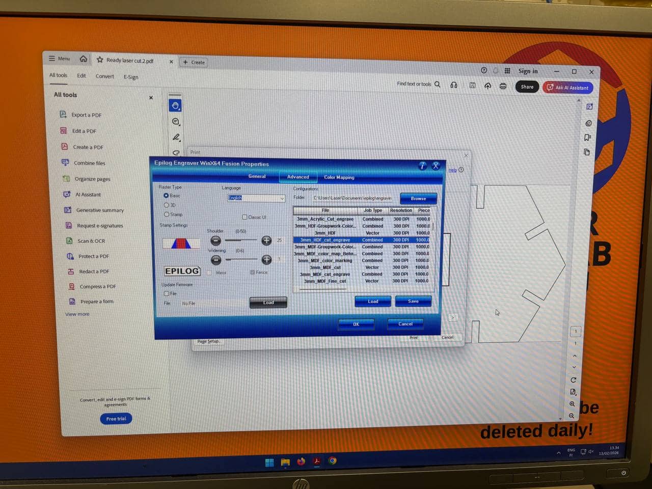
Fig. 6: Creating variations of the interlocking pieces.
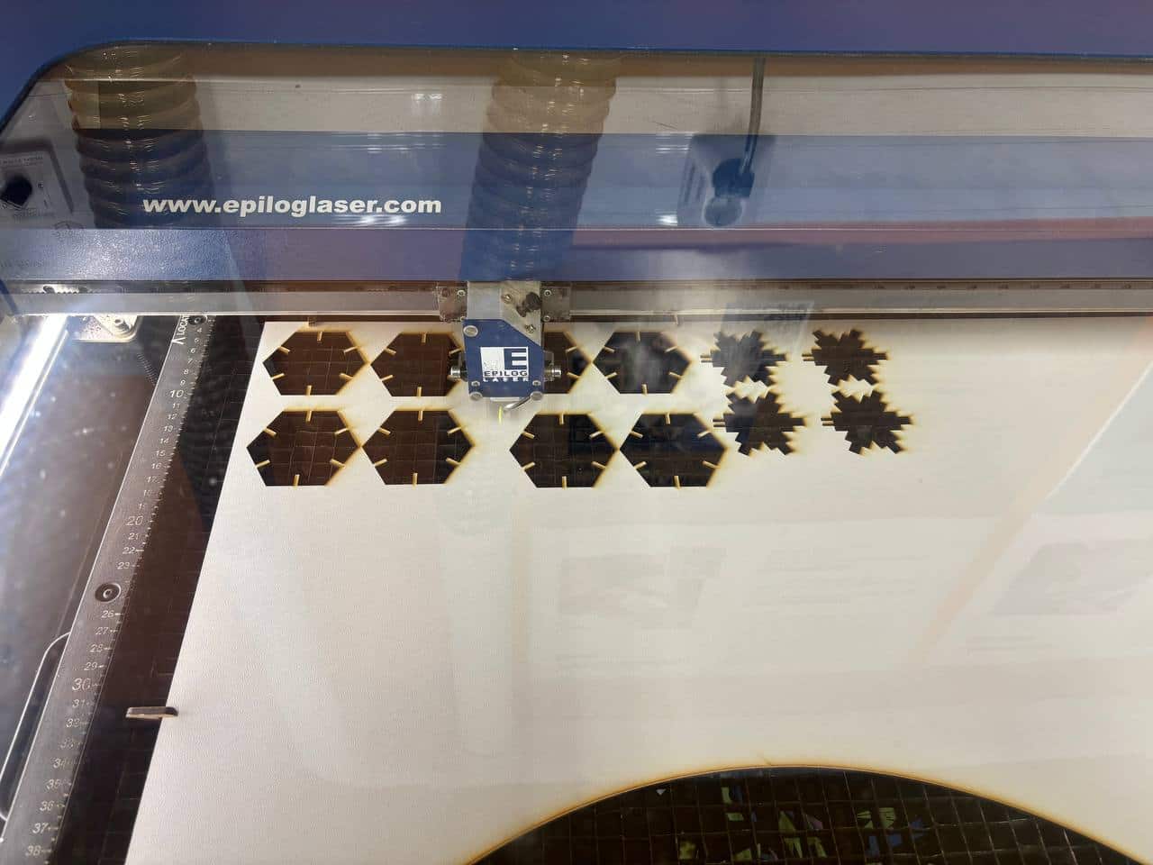
Fig. 7: 3D visualization of the complete construction module.
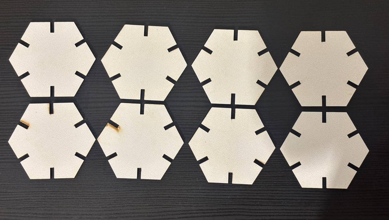
Fig. 8: Testing parameter updates to verify design flexibility.
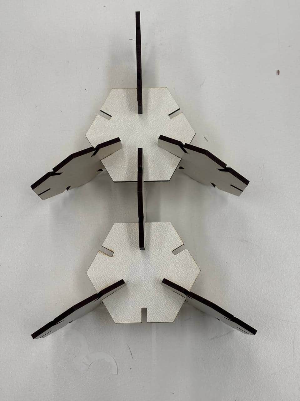
Fig. 9: Arranging the pieces on a 2D layout for cutting.
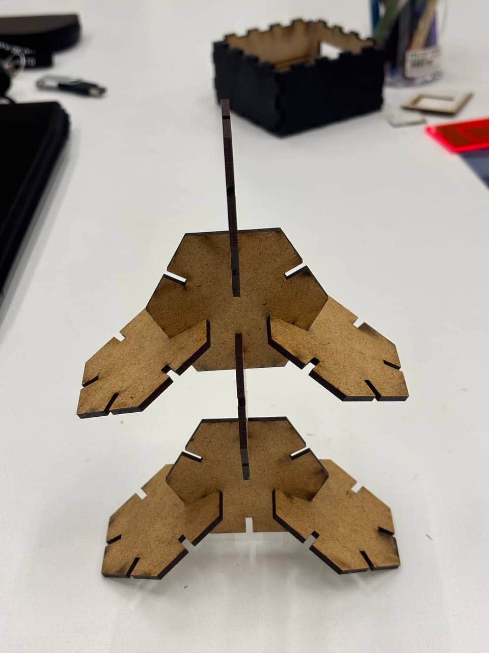
Fig. 10: Exporting the drawing from Fusion 360 to PDF.
3. Preparation and Laser Cutting Execution
To prepare the design for cutting, I followed these steps: First, I exported the design from Fusion 360 as a PDF. Then, I imported it into Inkscape, where I changed the line width to 0.02 mm (hairline) so the laser recognizes it as a cut line. Finally, I exported it again as a PDF. For the cutting process, I used the Epilog Fusion Laser, setting the origin to the top left, adjusting the focus manually, and configuring the job through the print driver with correct power and speed settings.
Vinyl Cutter
1. File Preparation (Design)
Vinyl cutting machines operate based on Vector lines. Designs should be created in software such as Inkscape. The execution file could contain filling but it's not necessary. Because the filling will be the color of the vinyl anyways. The reason that we choose no filling is that we want to see the lines and ensure there is no overlapping lines. After completing the design in Inkscape, open the file in the Roland CutStudio software to proceed with the output (printing/cutting). In CutStudio, the design will be placed in the bottom left automatically, which is the origin for vinyl cutting.
Vector vs. Raster: vinyl cutters require Vector files to function. Standard pixel-based images (such as JPEGs or PNGs) cannot be used for cutting because the machine requires specific paths to follow.
[Image of vector vs raster comparison]Industry Terminology: While we often use the word 'Print,' in the professional vinyl industry, this process is more accurately called 'Sending the cut job' or 'Outputting to the plotter.'
File Compatibility: When transferring my design from Inkscape to Roland CutStudio, I must save or export the file as an EPS or a DXF.
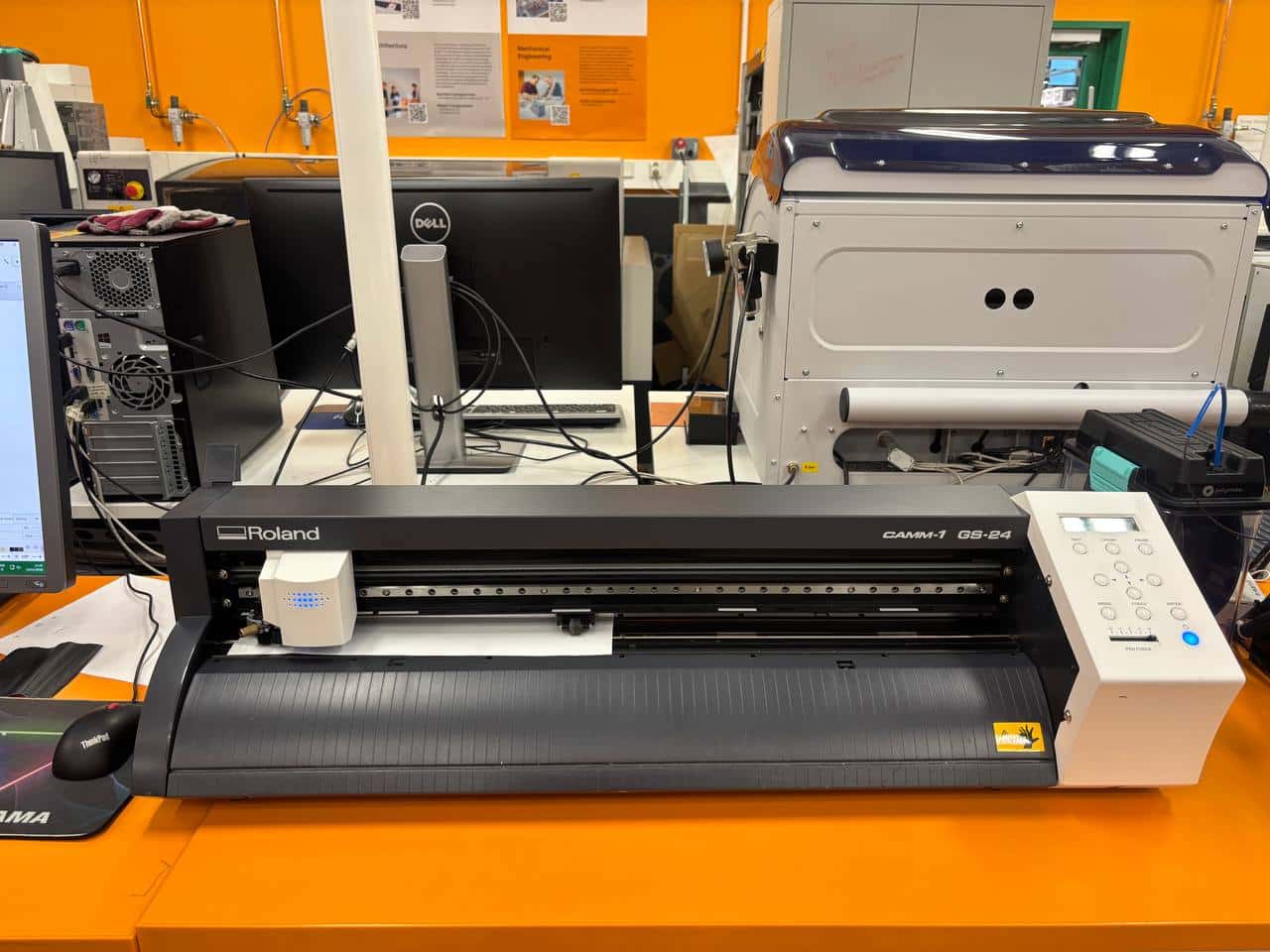
Fig. 11: The vinyl cutter machine during the cutting process.
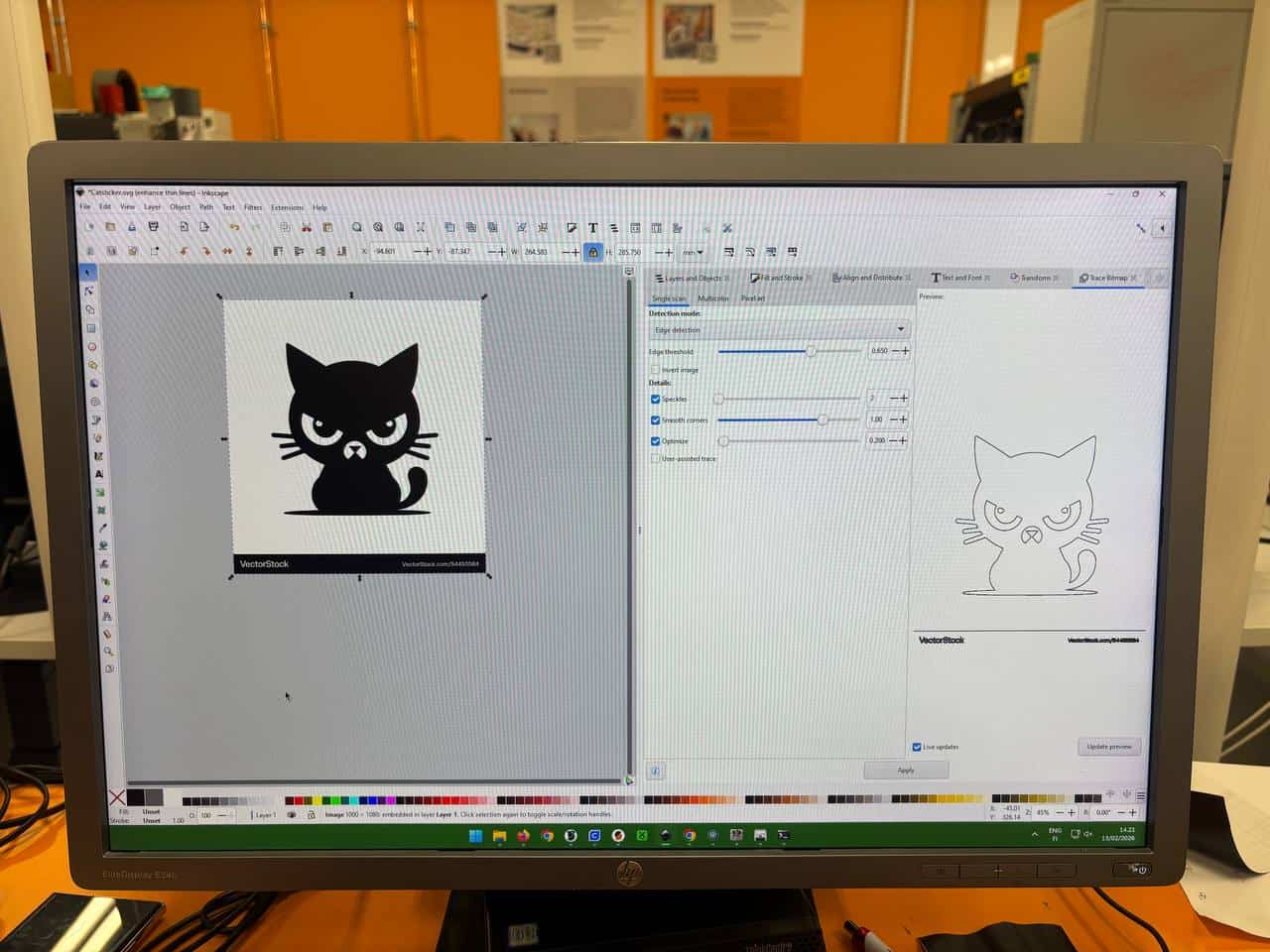
Fig. 12: Using the 'Trace Bitmap' feature in Inkscape to create vector paths.
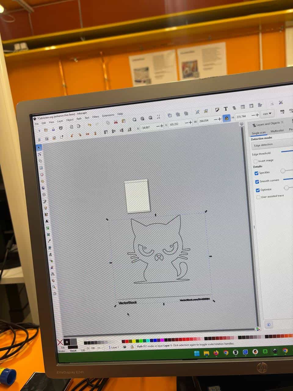
Fig. 13: Checking cutting lines and scaling the design.
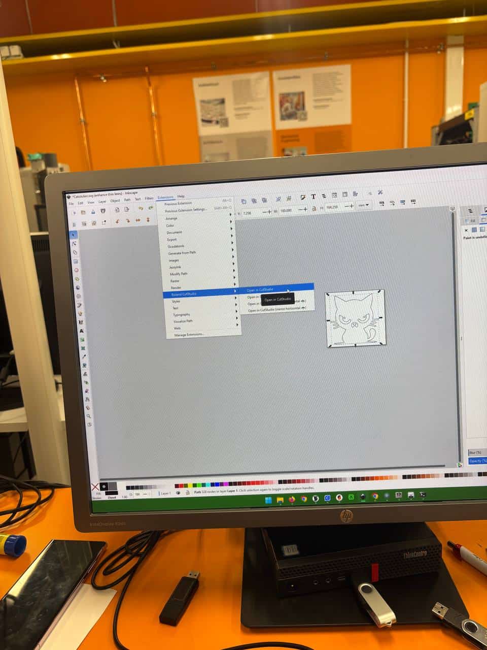
Fig. 14: Final preview before outputting the cut job.
2. Loading Vinyl into the Machine
- Release Lever: There is a lever located at the back of the machine. By pushing it down, the Pinch Rollers will be raised, allowing us to insert the paper into the machine.
- Alignment and Loading: If we are using a small piece of paper, we must set the machine's origin setting to "EDGE" and press ENTER.
- Vinyl Rolls: If using a roll, feed the paper from the back of the machine.
- Critical Placement: We must ensure that the edges of the vinyl are positioned precisely under the Pinch Rollers. If they are not aligned correctly within the grit marks, the machine will display a "Bad Position" error.
- Locking and Initialization: Once the vinyl sheet is perfectly aligned, pull the lever back up to lock the material in place. Finally, press the Enter button to allow the machine to calculate the cutting area.
3. Knife Blade and Pressure Settings
This is the most critical stage for preventing damage to both the paper and the device:
- Blade Length: The blade should only extend from the Holder just enough to cut through the vinyl layer without damaging the paper backing (liner).
- Pressure Management: Excessive pressure or a blade that is too long can cause the design layers to separate or tear. For example, in the image below, the blade pressure was set too high, leading to over-cutting and tearing the design, which ultimately ruined the final product.
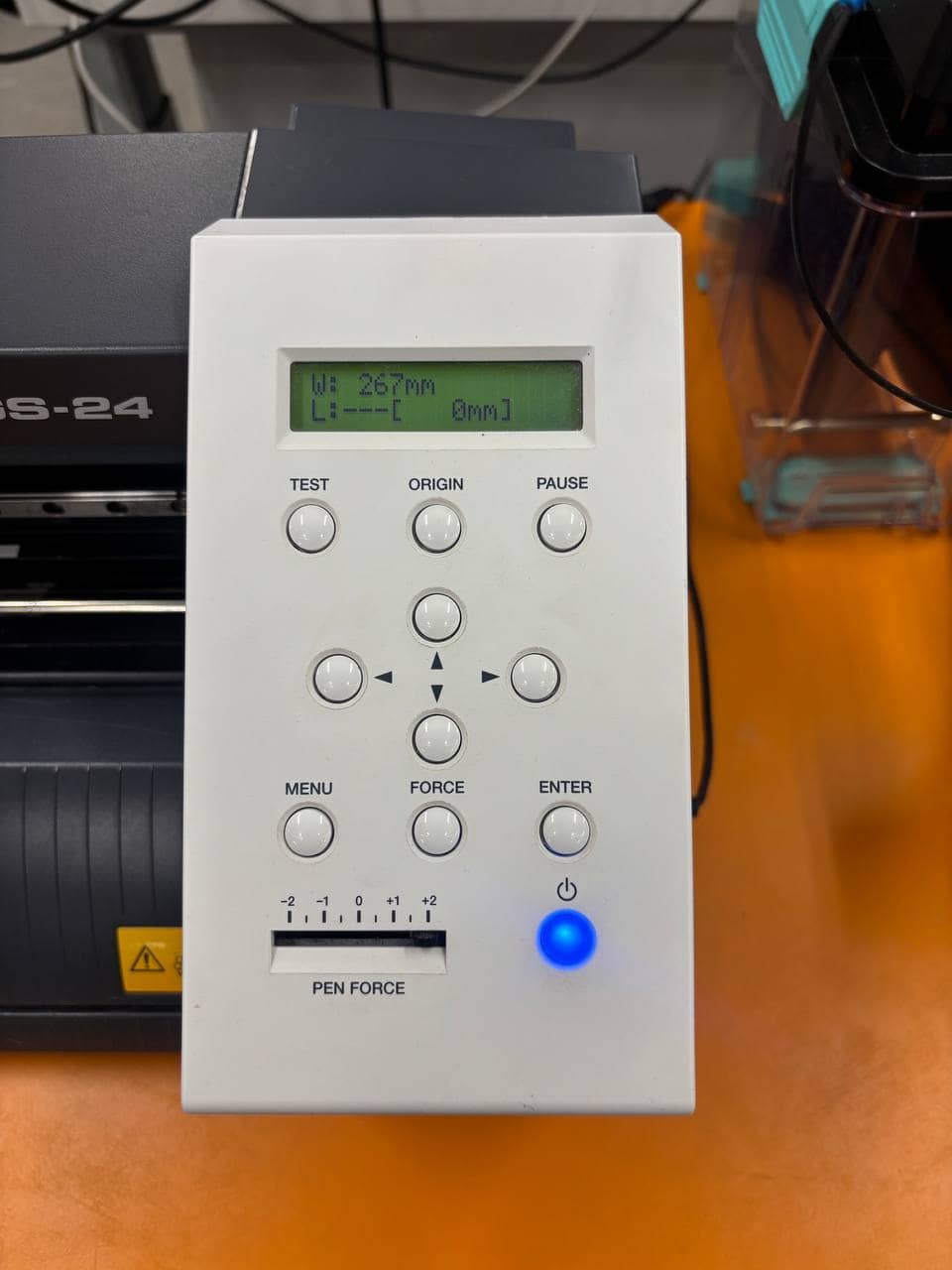
Fig. 15: Adjusting the Force: The Pen Force setting determines the downward pressure on the blade.
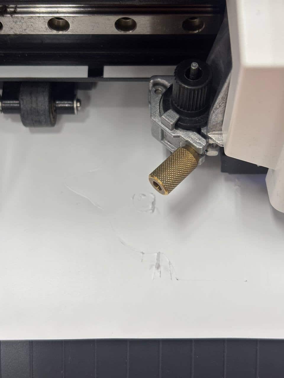
Fig. 16: Visible Damage: Example of tearing caused by excessive pressure during cutting.
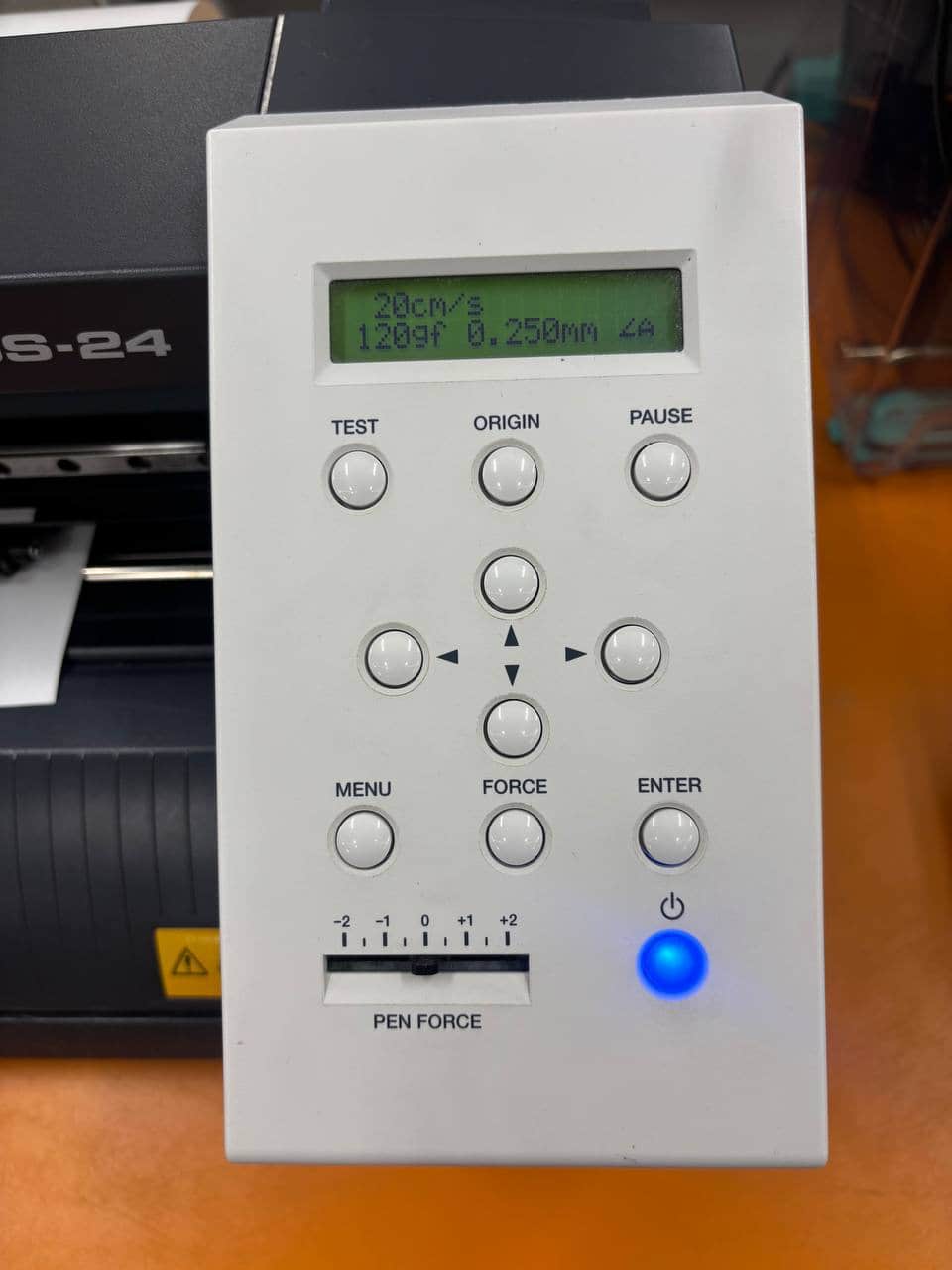
Fig. 17: Reducing Pen Force: Lowering the force for a precise and clean cut.
4. Weeding and Final Placement
Removing Excess Material: After the cutting process is complete, use a Pair of Tweezers or a weeding tool to carefully remove the unwanted parts of the vinyl from the paper. This step happens before transferring the design.
- Using Transfer Tape: Once the weeding is complete, apply a layer of Transfer Tape over the vinyl design. Use a squeegee or a flat tool to press it down firmly, ensuring there are no air bubbles.
- Lifting the Design: Carefully peel the transfer tape back at a 180-degree angle. The vinyl design should lift off the backing paper and stick to the tape.
- Final Application: Position the design onto your target surface. Press firmly from the center outward.
- Removing the Tape: Slowly peel away the transfer tape, leaving only the vinyl design perfectly aligned.
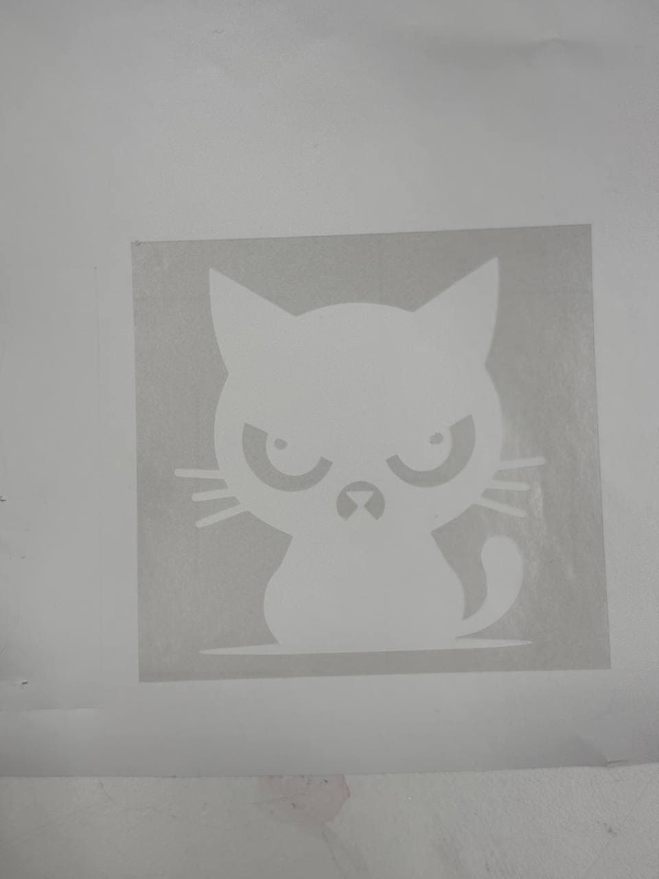
Fig. 18: Weeding out the excess vinyl material.
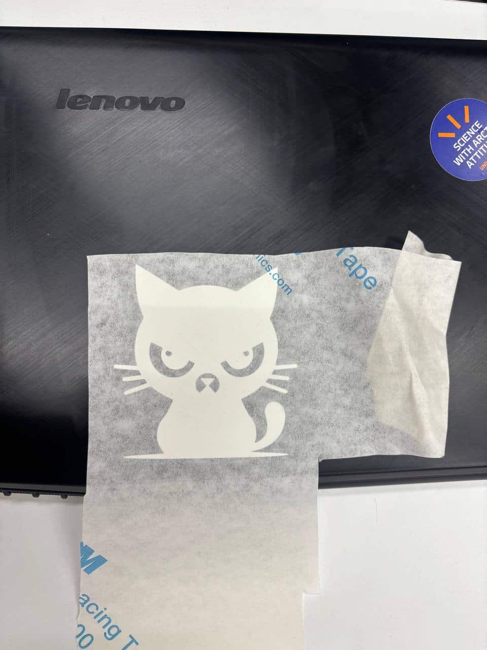
Fig. 19: Applying transfer tape to the weeded sticker.
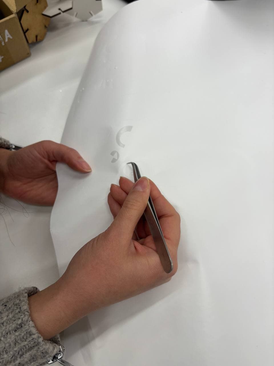
Fig. 20: Positioning the sticker on the target surface.

Fig. 21: Final result of the applied cat sticker.